Farm Operations Management
Plant Factory CO2 and HVAC: Airflow Beats Dosing
Articles for Farm Operations Managers
The checklist has a tick mark on every line again today. CO2 at 1000ppm, HVAC running as set. On paper, the operation passes. Yet the yield doesn’t match that passing grade. Raise the dosing and it hits a ceiling partway, and unevenness in growth lingers from one shelf spot to the next. The cause usually isn’t any single piece of equipment, but the “in between” of one piece and the next. As long as you run the CO2 enrichment equipment and the HVAC unit separately, it’s a place that keeps getting overlooked. Recast what flows in between — the airflow — as a single pipe, and the reason for the ceiling, the knack of designing them to work together, and the outlook for recovering the cost all start to look connected.
But let me say up front: airflow isn’t the only reason the back rows slow down. A drop-off at the edge of the light, local unevenness in temperature or humidity, or a scatter in nutrient delivery at the roots all produce the same symptom. So the real entry point of this article is “when the back slows down, first sort out which of airflow, light, temperature, or nutrient delivery is at work,” and airflow is one of the candidates. From there, we’ll trace the one thread of airflow that tends to get overlooked.
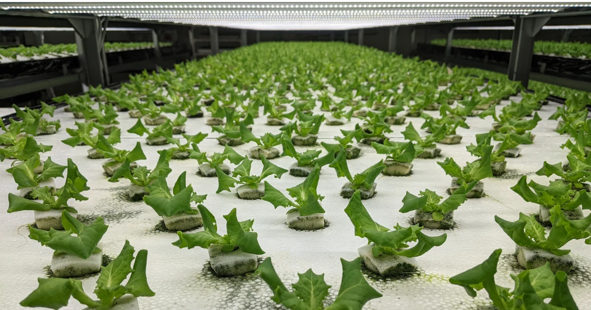
The meter reads 1000, yet only the back rows fail to grow
Only the back rows fail to grow. Even though the meter is pointing at 1000ppm.
In a vertical farm, CO2 often runs as “hold it at 1000ppm” and HVAC as “keep to the setpoint,” each watched by a different person, on a different meter. So when you have a block whose growth slows even though CO2 should be held at 1000ppm, your first thought is that photosynthesis has hit a ceiling. But look closely and, within the same room, the rows near the HVAC outlet are fine, and only the far back rows are slow. Once that’s the picture, this is less a CO2 problem than a question of whether the air is moving or not — as if the CO2 is thin only around the leaves.
In a fully closed PFAL growing leafy greens, with the light kept constant by LEDs, “not enough light” can’t explain why growth differs from row to row. The meter may point at 1000, but that’s the value at some one point in the room, and there’s no guarantee the air around the leaves in the back rows is the same. The question is “how much actually reaches the leaves,” yet as long as you look at the room’s single-point meter and at the CO2 enrichment unit and HVAC separately, that gap stays invisible.
Whether it reaches the leaves is decided by airflow, not by amount
A leaf running photosynthesis takes up the carbon dioxide right next to its surface and forms a thin film-like layer there. It’s called the leaf boundary layer, and when the air there isn’t moving, what’s been taken up isn’t replenished and stays thin. The concentration around the leaf is, in the end, decided by a subtraction: “how much of what the leaf took up does the air carry back in.” Even with the room meter pointing at 1000ppm, I’d say it wouldn’t be strange for the leaf surface in the back rows to have dropped to something like 600 to 700ppm. Does that ring a bell?
In other words, it looks like a problem of CO2 amount, but it’s really a problem of “the work of carrying.” No matter how many enrichment units you add to push the whole room to 1200 or 1300ppm, if there’s no movement around the leaf the boundary layer stays thin, and the back rows stay slow all the same. Conversely, the rows near the outlet exchange their air even with weak airflow, so at the very same 1000ppm it reaches them properly.
That said, row-to-row unevenness isn’t decided by airflow alone. It also happens with a drop-off at the edge of the light, with local humidity differences, or with a scatter in nutrient delivery at the roots. Airflow is one of those, and that’s exactly why — as we’ll get to later — you need to measure and sort it out instead of deciding by assumption.
There are two paths by which the concentration around the leaf breaks down, depending on how you dose. One is when, trying to dose the whole room uniformly, the CO2 that comes out is warmed, turns less dense, and gathers up high by convection. It’s the physics of warm, buoyant CO2 collecting up top, and it’s been observed in CFD simulation studies of greenhouses (Ref. 1). The other is when, in a place where the air doesn’t move like the back rows, what the leaf took up isn’t carried back in and the boundary layer stays thin. The first is “it escapes upward,” the second is “it arrives but doesn’t get exchanged” — different things are happening, but they share that both are cases where the assumption of “room single-point meter = leaf-surface concentration” falls apart. Greenhouses and closed types differ in form, but the physics itself — a warm, buoyant gas accumulating upward — doesn’t depend on the form. So if you dose locally, delivering close to the crop, you can raise at least the concentration around the leaf. How much reaches it is decided not by the amount you push in, but by the dosing method and how you make the airflow.
What’s more, since temperature and the environment inside the room vary quite a bit from place to place, a single-point sensor can’t represent the uniformity of the whole room, and you can’t grasp the real unevenness without looking at several points — that’s been reported in actual measurements too (Ref. 4). Not over-trusting a single-point meter isn’t a hunch; it’s the logic of how to measure.
You make airflow work by how you distribute it, not by total volume
You try to strengthen the airflow in the back rows by raising the HVAC’s air volume, and now the dehumidification side shifts along with it. Haven’t you had this experience? You’re circulating air to take away the moisture raised by transpiration, but the moment you try to deliver CO2 to the back with that same air, you start worrying about whether the leaves in the near rows are drying out too much. Airflow is all connected on a single knob, so raise the back and the front won’t come up, and reach for the humidity and something else moves.
This feeling that “it’s all connected on one knob” is the hard part of leafy greens. Raise the air volume to reach the back, and at the front the airflow is too strong, transpiration runs, and it swings toward over-drying. Because you’re working the very same single pipe.
But here I’d want to separate “total airflow volume” and “how airflow is distributed” as two different things. Try to bring the back up with the total-volume knob of air volume alone, and the front tends to be sacrificed. What really works is the distribution side, and you can touch that separately from the HVAC unit itself. For instance, add a small circulation fan only in the windless zone in the back to stir the air. That’s a job, independent of the main airflow used for dehumidification, of moving just the boundary layer in the back. Without raising the total volume, you carry back in just the one thin spot. But don’t keep the airflow hitting the leaves directly; flow it over or to the side of the plants. Keep blowing straight on them and the leaves get damaged.
And the reason the knobs all look connected is also that you stand on the assumption that humidity is always “taken away by airflow.” As long as you saddle the air volume with the job of dehumidification, every time you reach for the humidity the airflow moves and the photosynthesis side wobbles too. Here, if you have equipment with dedicated dehumidification capacity, the job of lowering the whole room’s absolute humidity can be shifted onto that capacity. But carrying out the water vapor that has built up around the leaf is still airflow’s job. So even if you move the lead role of dehumidification over to the HVAC unit, you still separately need airflow as the agitator at the leaf surface. It comes down to thinking of the knob at two scales: “the whole room’s humidity” and “exchanging the air around the leaf.” How to design the humidity around the leaf itself is worth going into separately, as designing the VPD.
When actually nailing down distribution, what I’ve relied on at PFAL sites is a few simple placements. Set the blowers facing each other so their airflows don’t cancel out and instead make one circuit of the room. Corners where the air struggles to wrap around are the usual suspects for dead air, so hit them intensively. Between the shelves of a multi-tier rack, slip in an auxiliary small fan to help each layer exchange. And use direction deliberately: vertical airflow when you want to even out the temperature difference between rack layers, horizontal airflow when you want to make a single wide grow bed uniform. In many cases, only by combining these two do the blind spots disappear. None of it is large-scale equipment; it’s adjusting how you distribute.
In experiments too, when leafy greens are grown in a sealed chamber, growth is best when the air speed around the leaves is roughly 0.3 to 0.5 m/s, and once it exceeds 0.6 m/s the airflow is too strong and dry weight actually drops. In the same single-facility experiment — confounders such as differences in growth stage remain — it was reported that making the airflow uniform brought the plant-to-plant variation (the standard deviation of dry weight) down from about 23% to nearly half that, so the plants became more even (Ref. 5). Airflow isn’t better the stronger it is; it’s something you distribute to the thin spots, neither too much nor too little.
The range where adding CO2 works, and judging what you can recover
Delivering it around the leaf, neither too much nor too little — that’s been the distribution story so far. Only once the airflow is in order can you honestly discuss “how far does adding CO2 work.” Put the other way, talking concentration alone while the carrying is clogged gets you nowhere. On that footing, from here it’s about money. Let’s think of it in two stages.
First, as a basic premise, adding CO2 works “only while nothing else is the limiting factor.” Fully artificial-light leafy greens are managed with both light and temperature held constant, so under those conditions there’s a ceiling on the CO2 that photosynthesis can use. Roughly from the ~400 ppm of ambient air, yield rises in proportion to what you add, but above a certain concentration the curve flattens out, and the increment in yield from adding more gets steadily smaller. That’s what the ceiling really is, and from there on you’re paying for less and less in return — what I’ll call “just paying.”
As for where that “certain concentration” is: in fact, in one hydroponic lettuce experiment, raising CO2 from 500 to 800 µmol/mol (roughly the same yardstick as ppm) increased fresh weight and dry weight, yet raising it further from 800 to 1200 showed no additional increase — a saturation pattern was reported (Ref. 6). By the literature’s yardstick, saturation begins around 800. That said, this saturation point shifts with cultivar and light level, and there are reports of increases beyond 800, so it’s just one yardstick. In another study too, while raising CO2 does indeed raise the photosynthetic rate, how it works depends on light intensity and the combination of light sources, and seen as a canopy it approaches saturation the more you raise the concentration — that’s been measured and modeled (Ref. 7, 8).
So as a management call, the landing point is somewhere around taking the literature’s saturation near 800 into account while setting the operating target around 1000. Not stopping at 800 just because saturation starts there, but factoring in the site’s unevenness and leaving a little headroom above — roughly that much on top. Raising the target to 1200 or 1300 is, by the literature’s saturation point, already on the “just paying” side, a place to tread carefully.
But here it connects back to the first half. The meter’s number and the amount the leaf can actually take up diverge. If the meter reads 1000ppm but the leaves in the back rows can take up only less than that, then in those back rows the ceiling hasn’t arrived yet. It hasn’t arrived, yet it shows up disguised as a ceiling — “adding CO2 doesn’t grow them.” This is the pattern that throws away the most money. CO2 isn’t really the limiting factor, carrying is, yet you add enrichment units or raise the cylinder concentration, piling up investment that doesn’t work. On the month-end books, all that’s left is a cost you can’t recover: “the CO2 bill went up but the yield didn’t change.”
So as a way to look at cost-effectiveness, sorting out where the limiting factor is comes first. Limited to a site where the back rows are slow and a hung strip of paper or a two-point measurement has confirmed no airflow, the first thing to add may not be expensive CO2 but redirecting airflow at the stagnant back, or adding a small fan in the few-thousand-to-tens-of-thousands-of-yen range (we’ll touch on how to confirm this in the next section). Because this fixes the carrying around the leaf, it raises the very efficiency of CO2. It’s an investment that makes the CO2 you already added start to work. Reverse the order — raise the concentration alone while the carrying stays narrow — and you only pile rich CO2 into the room across a thin leaf boundary layer, and the enrichment unit, the cylinder, and the electricity bill all go to “just paying.”
Electricity is a heavy cost to begin with. According to a review of PFAL vertical farms, electricity accounts for roughly 20 to 40% of production cost, of which lighting uses a little under 80–90% (Ref. 9). This is the range of values in industry literature, not the ratio of your own facility itself, but it doesn’t change that HVAC and lighting electricity is a thick layer even within overall operating cost. For what it’s worth, the added electricity of a small fan aimed at the stagnant back is, against this HVAC-and-lighting total, smaller by orders of magnitude — not a size to agonize over here. The question is whether the airflow you’re making with that electricity is stagnating and going to waste before it reaches the leaves. The effect of electricity, that heavy line item, comes down in the end to how the airflow reaches.
As a yardstick for recovery, don’t look at the CO2 line item on its own. Optimize the cylinder cost, the enrichment unit, and the dehumidification electricity as separate line items, and it’s the same tug-of-war as before: cut one and another stops working. What you want to see is the single point of “is each yen you put in turning into CO2 the leaf can actually take up,” but measuring the effective CO2 around the leaf directly isn’t easy. So in practice you place your bet indirectly, on the overlap of the row-to-row CO2 concentration difference and the yield difference (we’ll touch on how to measure that in the next section). As long as that point is clogged with carrying, recovery stays slow no matter which line item you touch. Conversely, if that point is open, then even modest dosing of around 1000ppm puts what you add squarely onto yield and gross margin. When you look at recovery on a multi-year profitability basis — how many years it takes to recoup the capital investment — whether this one point is open is the premise first. Not mistaking the ceiling for a carrying clog: that’s the biggest fork between recovering and just paying.
Showing the limiting factor in a cheap, visible form, and where to hand off to a specialist
Even if you propose adding one small fan or changing the airflow direction, from the standpoint of those above you the talk turns to “will that really raise yield.” That the CO2 around the leaf was thin, too, gets written off as “just your imagination” unless you measure it properly. How can you put where the limiting factor is into a form you can show people? So: how far can you measure on site, and from where on does it become a matter for specialists or equipment? Let’s think about that line in three stages.
First, the range you can confirm cheaply on site. If all you’re doing is turning “it might be my imagination” into “it’s not my imagination,” you don’t need expensive gear. Hold out your hand and feel the airflow. Or, stick a thin strip of light paper or tissue to the tip of a stick and hold it out at leaf height. With just this, the fact that the back is windless shows up to anyone’s eye. Film it and you have material to show the people above as is. At the front the paper flutters; in the back it hangs and doesn’t move. That one scrap conveys “the carrying is narrow” well enough.
If you want to add numbers to that, get one handheld CO2 sensor and one anemometer. They run from a few thousand to tens of thousands of yen, and you measure front and back at the same height and the same leaf position and line them up. The room meter at 1000ppm, but at the leaves in the back visibly lower and the air speed near zero. A table lining up these two points is the most effective way to show it. Even with only one sensor, you can come close by measuring front and back in turn, offset in time. How the airflow runs is decided by the placement of shelves and blowers, so with the same equipment it doesn’t waver day to day. So measuring air speed is enough done once when you’re sorting out the limiting factor; it’s not the kind of number you watch every day.
And the most important thing is to check that measurement against yield. What works is, more than the concentration number itself, the correspondence that if the yield in the back rows is lower than the front, then the fact of “yield low only in the back” and the fact of “CO2 thin and windless only in the back” overlap in the same place. Conversely, if the yield is even but only CO2 and air speed are off, the limiting factor may be somewhere other than airflow. That’s why you overlay them. If you’re putting in one small fan, or changing the direction, run a small trial comparing the back rows’ yield before and after. Fix just one block first and compare it with the untouched row next to it. Then you can judge whether a ten-thousand-yen-class fan is worth it from the harvest data you’re already taking.
From here on is the line where it becomes a matter for specialists or equipment. Think of the range you can handle on site and the range you hand off outside separately. Finding the thin spots with two or three points is the site’s job, but once you want to grasp how the air circulates across the whole room as a field, it enters the territory of monitoring that keeps taking many points at once, and it passes into the hands of measurement specialists. Placing your bet point by point is the site; designing it as a field is the specialist. Also, “distribution” — adding circulation fans or adjusting direction — you can handle on site, but “total-volume”-side design changes such as altering the HVAC unit’s own capacity or the position and number of outlets, or moving the lead role of dehumidification from air volume to dehumidification capacity, become equipment retrofits. And once you reach the point where, because of how the shelves are built or the shape of the room, the air won’t circulate even if you add a fan, you’re in the world of CFD, designing the airflow itself by calculation. The size of the investment call changes, so you hand off to a specialist after showing, with the paper’s movement and the two-point measurement on site, that something is “clearly wrong.”
In fact, studies using CFD analysis have shown that redesigning the position and structure of intake and exhaust openings can greatly improve the uniformity of indoor airflow distribution, and they report that — including making use of the LEDs’ heat dissipation (waste heat) in airflow design — it serves as a guide for design strategies that order the canopy airflow (Ref. 2, 3). Hand off to a specialist at the stage where the stagnation won’t structurally go away, and you can rework the layout by calculation rather than hunch. Put the other way, placing your bet up to that point can be covered well enough with the paper’s movement and a two-point measurement on site.
In the end, what you should do on site isn’t to measure precisely, but to show — cheaply, in a form anyone can see — your read that “this is the limiting factor.” A video of the paper’s movement, two-point CO2 and air speed, a one-block yield comparison. This set of three is enough in most cases, and only when a structural problem that even this can’t fully explain remains do you pass the baton to a specialist. Go into large-scale measurement or retrofits from the start, and you could end up paying money where the limiting factor isn’t.
Incidentally, how to supply CO2 — that is, choosing the equipment, whether a cylinder, a liquid-carbonic tank, or a combustion-type generator — is also a point that splits by scale and cost. But that’s the next stage’s story, premised on the airflow being open, and whichever method you choose, if it isn’t carried around the leaf the effect is impaired all the same. Comparing the equipment is enough to nail down separately after this article’s main thread (sorting out whether carrying or concentration is the limiting factor) is done.
Stop treating CO2 and HVAC as separate line items and separate equipment, and read them as one pipe of airflow that connects through to photosynthesis at the leaf. Do that, and the back rows slowing down, the money not coming back, and the moments to hand off to a specialist all explain themselves on one and the same chain.